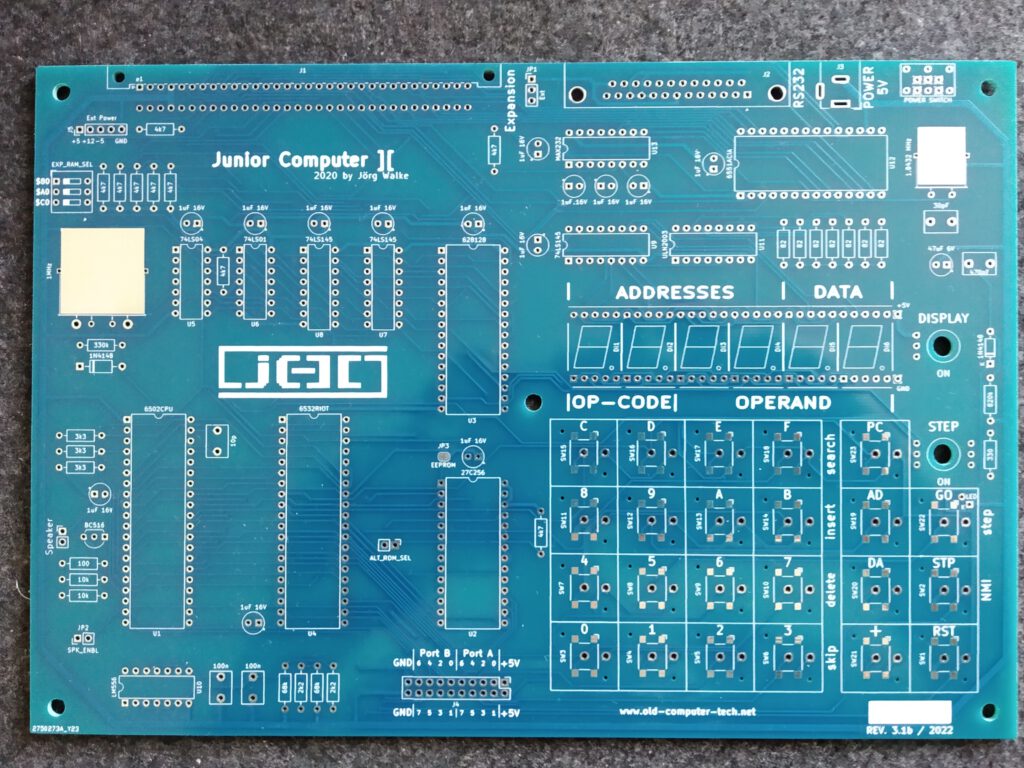
The revision 3.1B board with some minor changes. As an alternative, its now possible to solder some cheap SMD switches instead of useing the expensive Marquard keys. However, the look and feel isn’t the same. There is also a new jumper switch to select between the upper and lower part of the system ROM. So you can hold two different systems and change it on the fly. Also the new Junior Computer ][ logo is printed on the PCB.
The first assembled IO/Language Card with I2C Bus, Real Time Clock, user VIA ports, SPI interfaced SD-Card reader, SN76489 Sound Chip with audio amplifier, Datasette connector, parallel printer port, ASCII keyboard connector, and ROM for EhBasic or other programming languages.
Heavy programming sessions are coming up to bring it all alive…
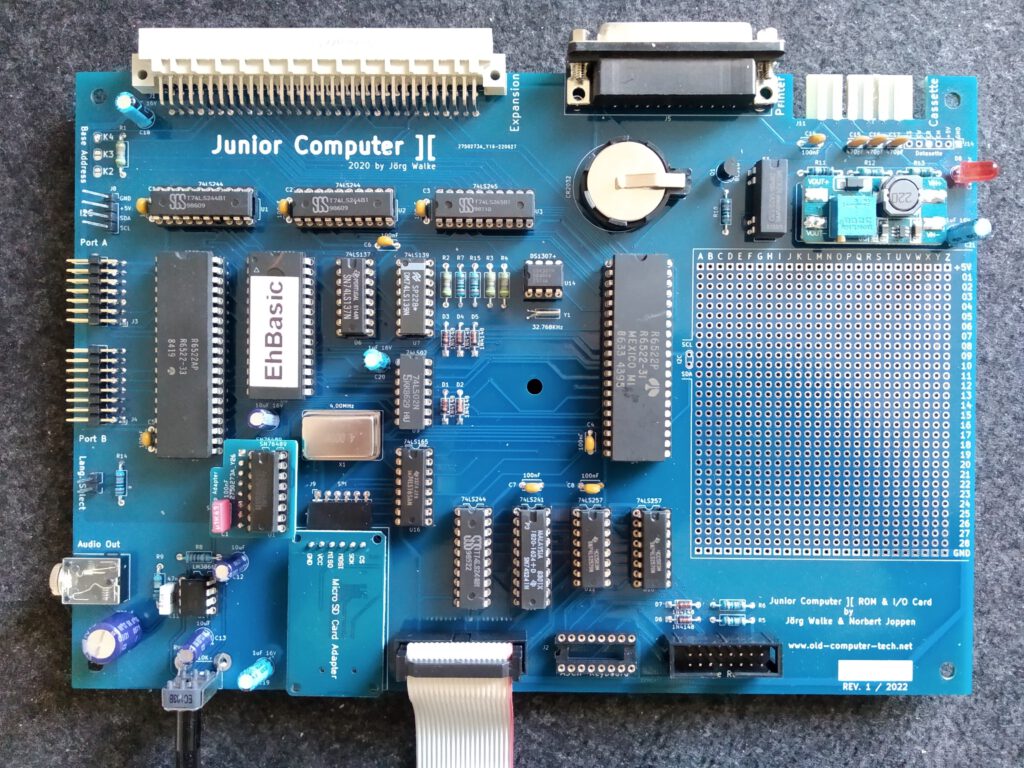
Because of a misunderstood datasheet for the Sound Chip, a little adapter PCB was necessary and on the bottom side of the PCB some extra diodes and resistors needed to be soldered. The marker notch of the Datasette connector was on the wrong position, so I used a saw to place it on the correct possition. The old notch is filled up with epoxy resin. Of course, the new circuit board no longer has these issues.
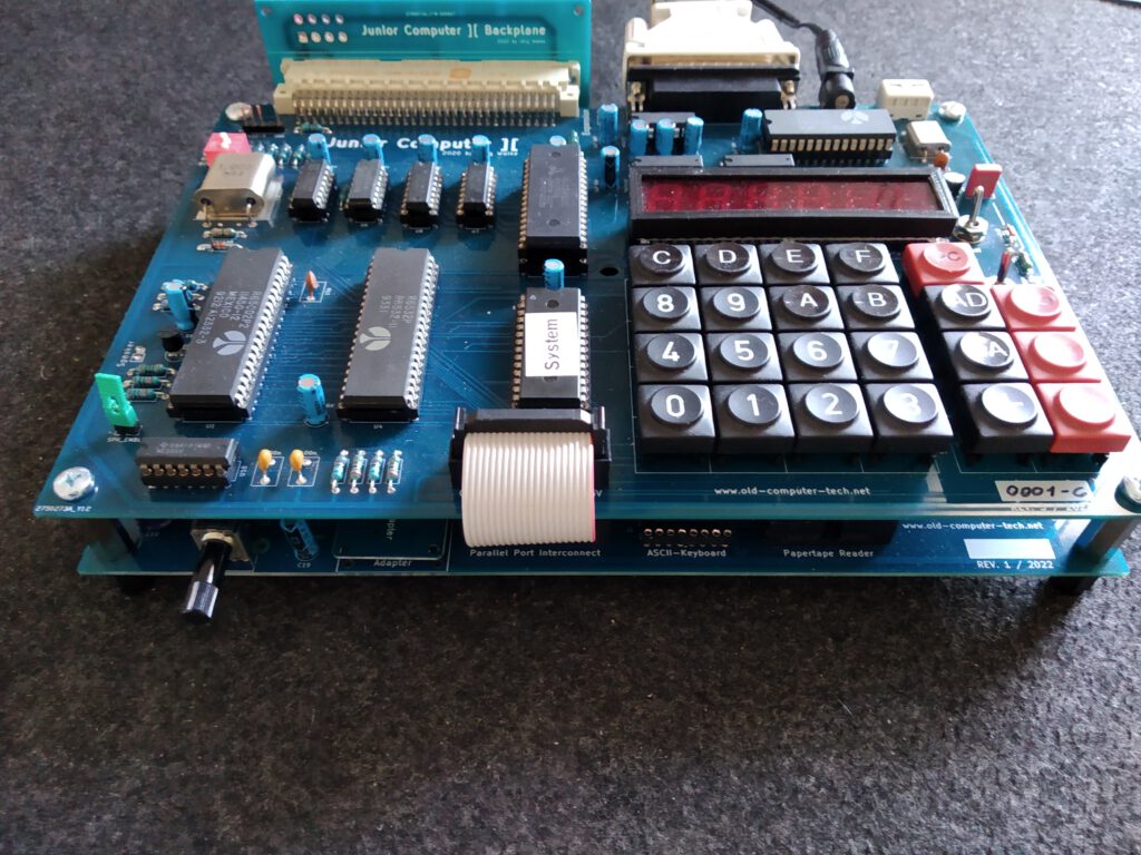
IO/Language Card stacked over the Junior Computer ][
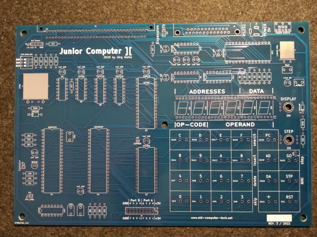
The new revision 3 boards has arrived
…all components assembled and soldered
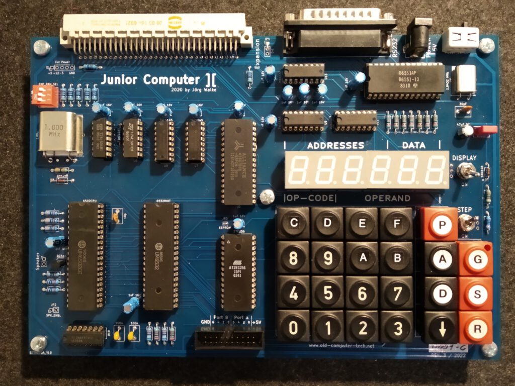
…and it works fine!
Its new features are: Up to 128KB RAM chips installable. 3 DIP switches to configure three additional 8KB RAM banks. Maximum of 51712 Bytes usable with 64KB RAM chip. Auto reset at power on. A power switch (oh yeah). Usable Memory for string buffers in the address area of the ACIA.
